“RV solar panel wiring diagram”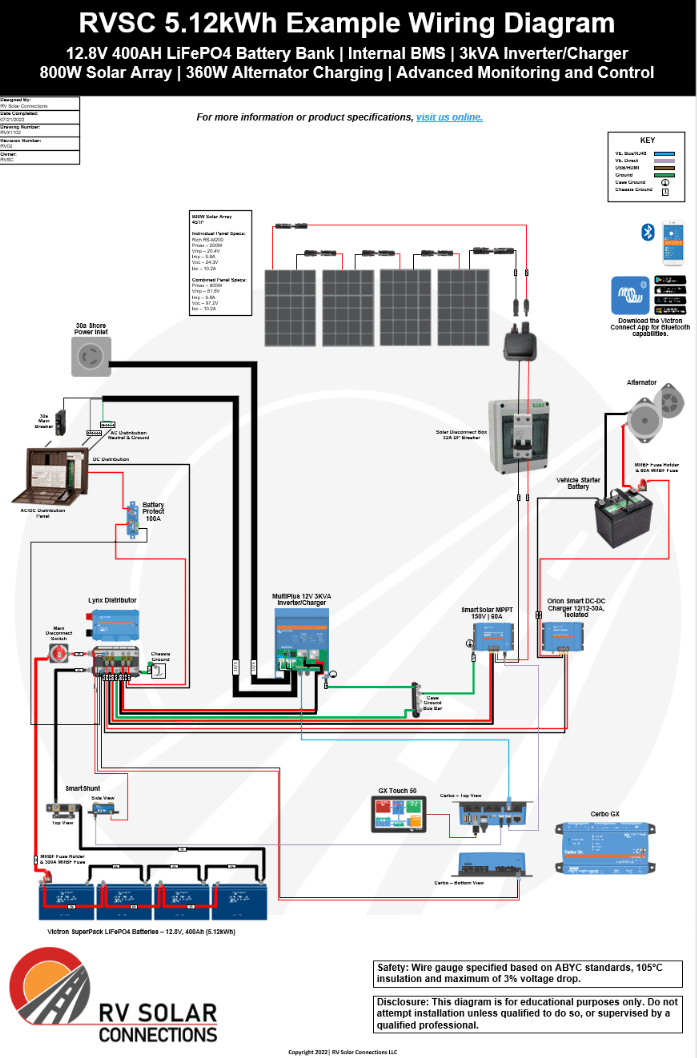
One of the most critical components of an RV solar system is the wiring diagram, which can be overwhelming for those new to solar power. In this article, we will delve into the world of RV solar panel wiring diagrams, exploring the basics, components, and best practices for designing and installing a solar system for your recreational vehicle.
Introduction to RV Solar Panel Systems
Before diving into wiring diagrams, it’s essential to understand the basic components of an RV solar panel system. A typical system consists of:
- Solar Panels: These are the photovoltaic (PV) panels that convert sunlight into electrical energy.
- Charge Controller: This device regulates the flow of energy from the solar panels to the battery, preventing overcharging and ensuring safe operation.
- Battery: Deep cycle batteries, such as lead-acid or lithium-ion, store the energy generated by the solar panels for later use.
- Inverter/Charger: This device converts DC power from the battery to AC power for appliances and charges the battery from an external power source, such as a generator or shore power.
Understanding RV Solar Panel Wiring Diagrams
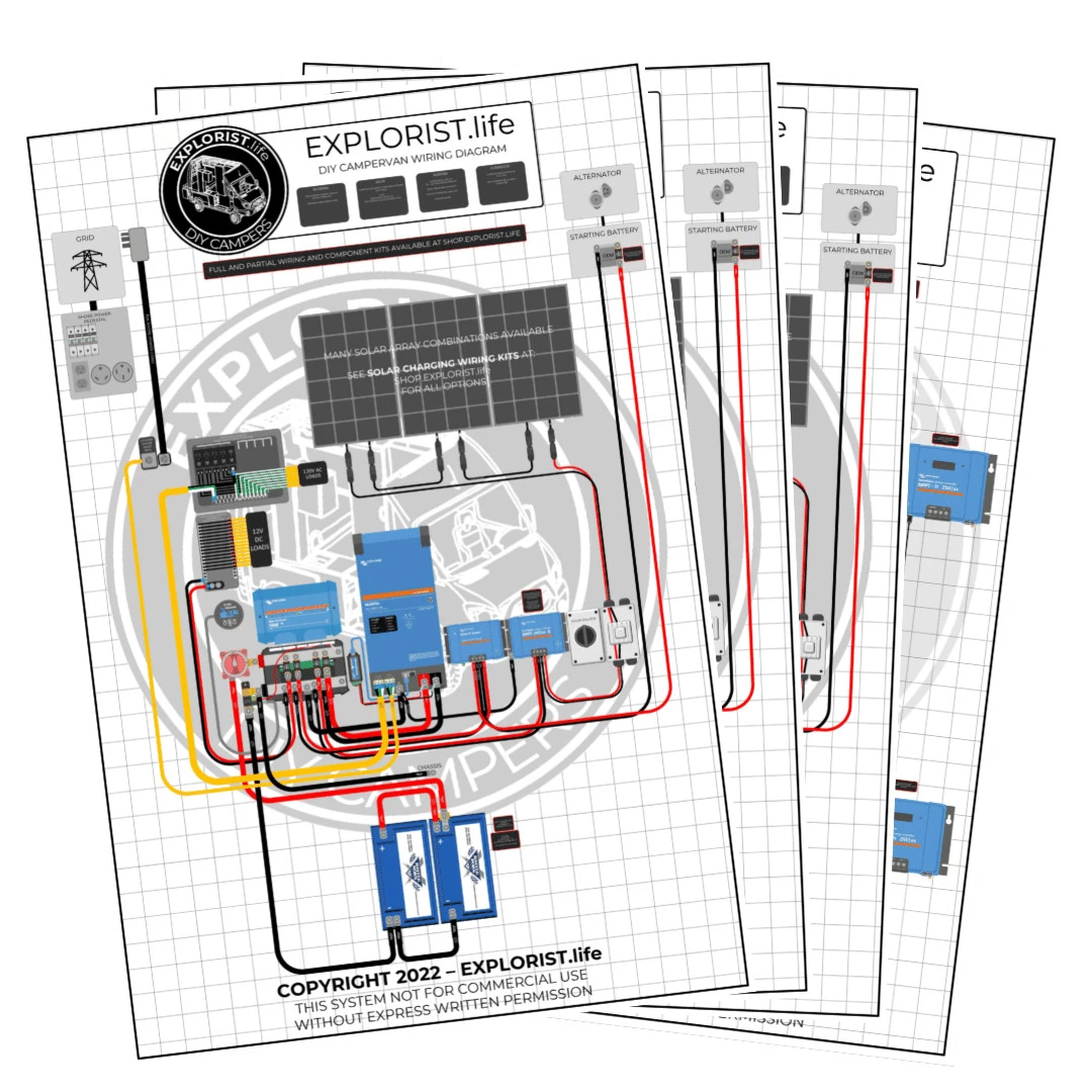
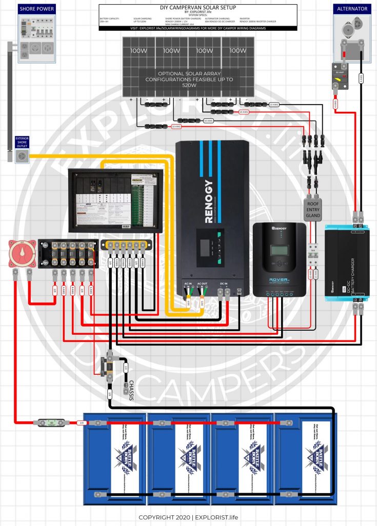
A wiring diagram is a visual representation of the electrical connections between components in an RV solar system. It’s a crucial tool for designing, installing, and troubleshooting the system. A typical RV solar panel wiring diagram includes:
- Solar Panel Array: The diagram shows the connection of multiple solar panels in series and/or parallel to achieve the desired voltage and current.
- Charge Controller Connection: The charge controller is connected to the solar panel array, battery, and other components, such as the inverter/charger.
- Battery Connection: The battery is connected to the charge controller, inverter/charger, and other DC loads, such as lights and appliances.
- Inverter/Charger Connection: The inverter/charger is connected to the battery, shore power, and AC loads, such as appliances and outlets.

Components of an RV Solar Panel Wiring Diagram
When designing or interpreting an RV solar panel wiring diagram, it’s essential to understand the various components and their symbols. Some common components include:
- Solar Panels: Represented by a symbol resembling a sun, solar panels are connected in series and/or parallel to achieve the desired voltage and current.
- Charge Controller: Symbolized by a box with a temperature sensor and a battery temperature sensor, the charge controller regulates the flow of energy from the solar panels to the battery.
- Battery: Represented by a symbol resembling a battery, deep cycle batteries store energy for later use.
- Inverter/Charger: Symbolized by a box with an AC output and a DC input, the inverter/charger converts DC power to AC power and charges the battery from an external power source.
- Fuses and Circuit Breakers: These components protect the system from overcurrent conditions and are represented by symbols resembling a fuse or a circuit breaker.
- Wiring: The diagram shows the connection of components using wires, which are represented by lines with arrows indicating the direction of current flow.
Best Practices for Designing an RV Solar Panel Wiring Diagram
When designing an RV solar panel wiring diagram, follow these best practices:
- Keep it Simple: Avoid complex diagrams with multiple branches and connections.
- Use Standard Symbols: Use standardized symbols for components to ensure clarity and consistency.
- Label Components: Label each component clearly, including the solar panel array, charge controller, battery, and inverter/charger.
- Show Wire Sizes and Colors: Include wire sizes and colors to ensure correct wiring and minimize errors.
- Consider Safety: Include safety devices, such as fuses and circuit breakers, to protect the system from overcurrent conditions.
Common RV Solar Panel Wiring Diagram Configurations
There are several common configurations for RV solar panel wiring diagrams, including:
- Series Configuration: Solar panels are connected in series to achieve a higher voltage, with the charge controller regulating the flow of energy to the battery.
- Parallel Configuration: Solar panels are connected in parallel to achieve a higher current, with the charge controller regulating the flow of energy to the battery.
- Series-Parallel Configuration: A combination of series and parallel connections, this configuration offers a higher voltage and current.
Troubleshooting RV Solar Panel Wiring Diagrams
When troubleshooting an RV solar panel system, refer to the wiring diagram to identify potential issues. Common problems include:
- Overcharging: Check the charge controller settings and wiring connections to ensure proper regulation of energy flow to the battery.
- Undercharging: Verify the solar panel array is receiving sufficient sunlight and the charge controller is functioning correctly.
- Short Circuits: Inspect the wiring diagram and connections for signs of damage or wear, and check for short circuits between components.
Conclusion
RV solar panel wiring diagrams are a crucial tool for designing, installing, and troubleshooting solar systems for recreational vehicles. By understanding the components, symbols, and best practices for creating a wiring diagram, RV owners can ensure a safe and efficient solar system. Whether you’re a seasoned solar enthusiast or just starting to explore the world of renewable energy, this comprehensive guide provides a solid foundation for navigating the complexities of RV solar panel wiring diagrams. With the right knowledge and tools, you can harness the power of the sun to fuel your adventures and reduce your reliance on traditional energy sources.