“Solar system breaker box wiring diagram”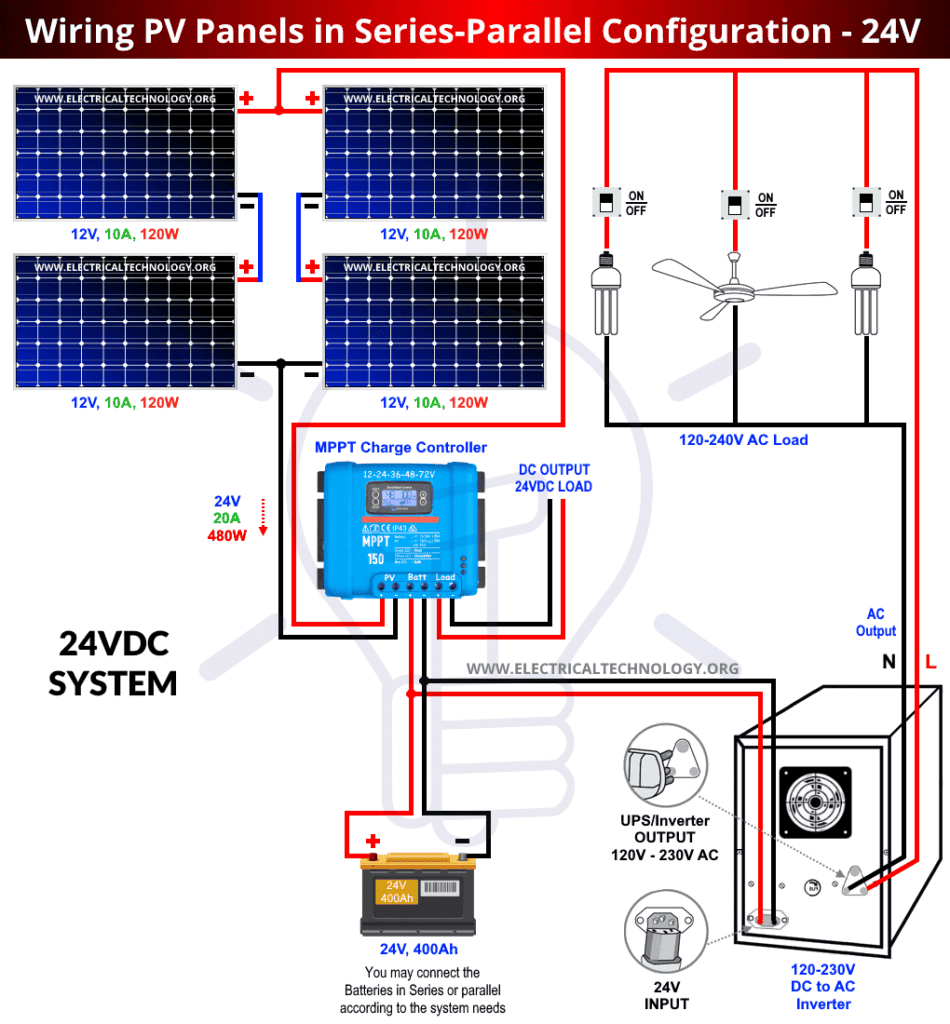
One crucial component of a solar power system is the breaker box, also known as the main electrical panel or load center. The breaker box serves as the central hub for distributing electrical power throughout a building or home. In this article, we will delve into the world of solar system breaker box wiring diagrams, exploring their significance, components, and how to read and create them.
What is a Breaker Box Wiring Diagram?
A breaker box wiring diagram, also known as a solar panel wiring diagram or electrical panel diagram, is a visual representation of the electrical connections within a breaker box. It illustrates the layout of the various components, including circuit breakers, wires, and electrical panels, and how they are connected to each other. The diagram provides a detailed overview of the electrical system, making it easier to understand, install, and maintain.
Importance of Breaker Box Wiring Diagrams
Breaker box wiring diagrams are essential for several reasons:
- Safety: A well-designed wiring diagram helps ensure the safe installation and operation of a solar power system. It identifies potential hazards and provides a clear understanding of the electrical connections, reducing the risk of electrical shocks, fires, or other accidents.
- Efficient Installation: A wiring diagram guides electricians and solar installers during the installation process, ensuring that all components are connected correctly and efficiently.
- Troubleshooting: In the event of an electrical issue, a wiring diagram helps identify the problem and facilitates troubleshooting, reducing downtime and repair costs.
- Code Compliance: A wiring diagram ensures that the electrical system meets local electrical codes and regulations, avoiding potential fines or penalties.
Components of a Breaker Box Wiring Diagram
A typical breaker box wiring diagram consists of the following components:
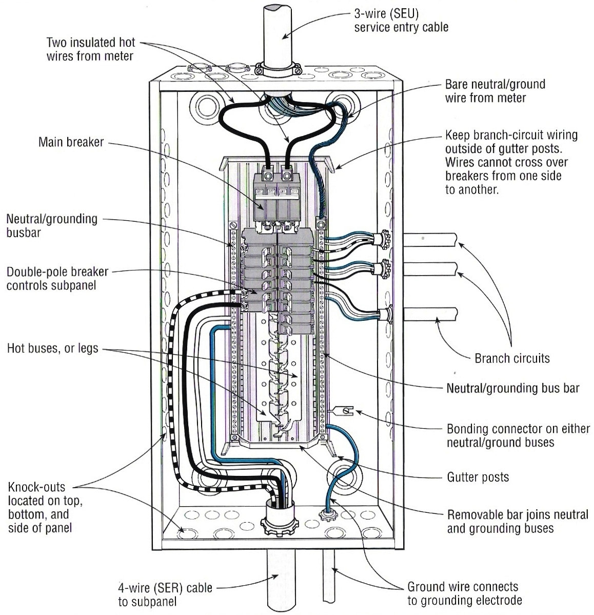
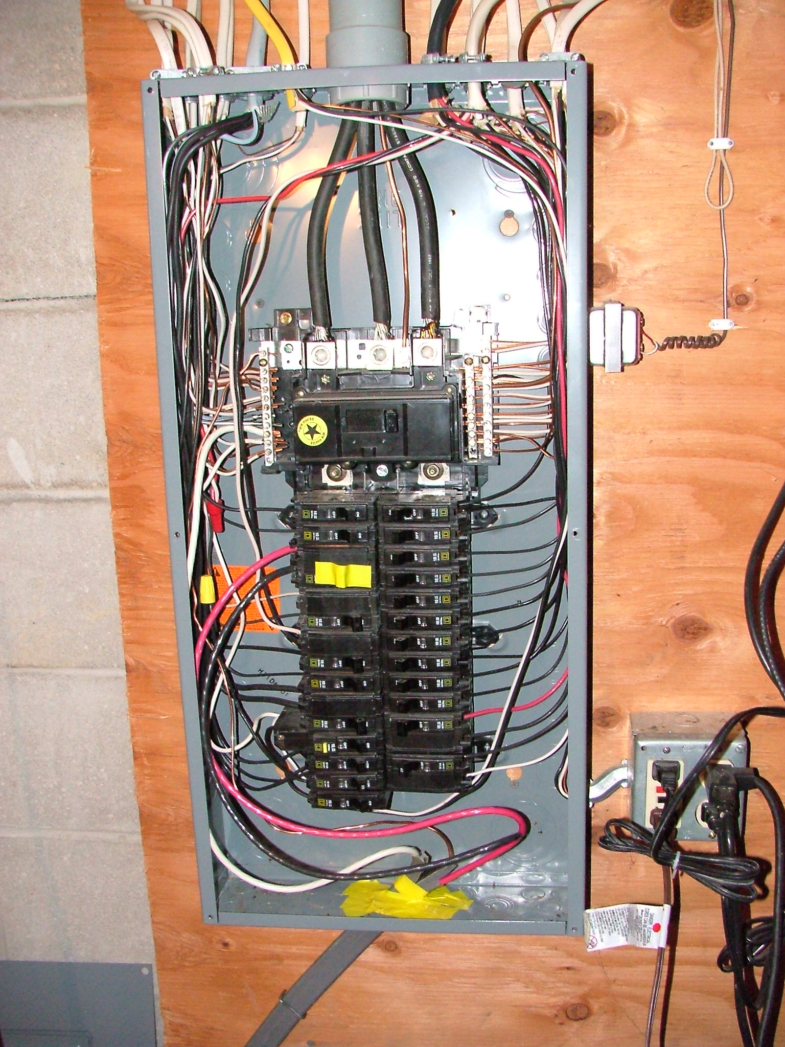
- Breaker Box: The main electrical panel or load center, which houses the circuit breakers, wires, and other electrical components.
- Circuit Breakers: Automatic switches that protect the electrical system from overloads, short circuits, and other faults.
- Wires: Insulated conductors that carry electrical power between components.
- Electrical Panels: Sub-panels or auxiliary panels that distribute power to specific areas or circuits.
- Grounding System: A network of conductors and equipment that provide a safe path to ground for electrical currents.
- Solar Panel Array: The collection of solar panels that generate electricity.
- Inverter: A device that converts DC power from the solar panel array to AC power for use in the electrical system.
- Mounting Hardware: Components that secure the solar panels, inverter, and other equipment to the building or structure.

Reading a Breaker Box Wiring Diagram
To read a breaker box wiring diagram, follow these steps:
- Identify the Components: Locate the various components, such as circuit breakers, wires, and electrical panels, and understand their functions.
- Understand the Wiring: Follow the wiring connections between components, noting the wire sizes, colors, and types.
- Determine the Circuit Path: Identify the flow of electrical power from the solar panel array, through the inverter, and into the breaker box.
- Note the Grounding System: Verify that the grounding system is properly connected and configured.
- Check for Safety Features: Ensure that the diagram includes safety features, such as circuit breakers, fuses, and surge protectors.
Creating a Breaker Box Wiring Diagram
To create a breaker box wiring diagram, follow these steps:
- Gather Information: Collect data on the solar power system, including the type and size of equipment, wire sizes, and electrical panel configurations.
- Choose a Diagramming Tool: Select a diagramming software or tool, such as AutoCAD, SketchUp, or Microsoft Visio, to create the wiring diagram.
- Draw the Components: Add the various components, including circuit breakers, wires, and electrical panels, to the diagram.
- Connect the Components: Draw the wiring connections between components, ensuring that the diagram is accurate and easy to follow.
- Include Safety Features: Add safety features, such as circuit breakers, fuses, and surge protectors, to the diagram.
- Review and Refine: Review the diagram for accuracy and completeness, making any necessary revisions or updates.
Best Practices for Breaker Box Wiring Diagrams
To ensure that your breaker box wiring diagram is accurate, efficient, and safe, follow these best practices:
- Use Standard Symbols: Use standard symbols and notations to represent components and wiring connections.
- Keep it Simple: Avoid clutter and complexity by using clear, concise labels and minimizing the number of components.
- Use Color-Coding: Use color-coding to differentiate between wires, components, and electrical panels.
- Include a Key or Legend: Provide a key or legend to explain the symbols, abbreviations, and notations used in the diagram.
- Update Regularly: Regularly update the diagram to reflect changes or modifications to the electrical system.
Conclusion
In conclusion, a breaker box wiring diagram is a critical component of a solar power system, ensuring safe, efficient, and compliant installation and operation. By understanding the components, reading, and creating a wiring diagram, you can ensure that your electrical system is properly configured and maintained. Remember to follow best practices, such as using standard symbols, keeping it simple, and including a key or legend, to create a clear and accurate wiring diagram. Whether you are a solar installer, electrician, or homeowner, a well-designed breaker box wiring diagram is essential for a safe, efficient, and reliable solar power system.