Solar Panel To Breaker Box Wiring Diagram
“Solar panel to breaker box wiring diagram”
However, installing a solar panel system can be a complex process, requiring careful planning and execution to ensure safety and efficiency. One crucial aspect of solar panel installation is the wiring diagram, which connects the panels to the breaker box. In this article, we will delve into the world of solar panel to breaker box wiring diagrams, providing a comprehensive guide for electricians, solar installers, and DIY enthusiasts.
Introduction to Solar Panel Systems
A solar panel system consists of several components, including the solar panels, a mounting system, an inverter, and a breaker box. The solar panels convert sunlight into direct current (DC) electricity, which is then sent to the inverter. The inverter converts the DC power into alternating current (AC) electricity, which is compatible with the grid and can be used to power homes and businesses. The breaker box, also known as the main electrical panel, is the central distribution point for the electrical power in a building.
Understanding the Wiring Diagram
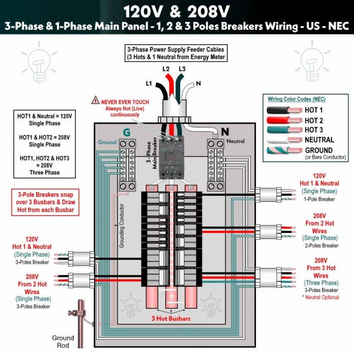
A wiring diagram is a visual representation of the electrical connections between the solar panels, inverter, and breaker box. It provides a detailed layout of the wires, cables, and connectors used to connect the various components of the solar panel system. A well-designed wiring diagram is essential to ensure safe and efficient operation of the system.
Components of a Solar Panel to Breaker Box Wiring Diagram
A typical solar panel to breaker box wiring diagram includes the following components:
- Solar Panels: The solar panels are the heart of the system, converting sunlight into DC electricity.
- Inverter: The inverter converts the DC power from the solar panels into AC power, which is compatible with the grid.
- Breaker Box: The breaker box is the main electrical panel, distributing power to the various circuits in the building.
- Wires and Cables: The wires and cables connect the solar panels to the inverter and the inverter to the breaker box.
- Connectors: The connectors join the wires and cables to the various components of the system.
- Fuses and Circuit Breakers: The fuses and circuit breakers provide protection against electrical surges and overloads.

Types of Wiring Diagrams

There are several types of wiring diagrams used in solar panel installations, including:
- Series Wiring Diagram: In a series wiring diagram, the solar panels are connected in a series, with each panel connected to the next in a linear sequence.
- Parallel Wiring Diagram: In a parallel wiring diagram, the solar panels are connected in parallel, with each panel connected to a common busbar.
- Combination Wiring Diagram: In a combination wiring diagram, the solar panels are connected in a combination of series and parallel configurations.

Designing a Solar Panel to Breaker Box Wiring Diagram
Designing a solar panel to breaker box wiring diagram requires careful consideration of several factors, including:
- System Size: The size of the solar panel system will determine the number of solar panels, inverters, and breaker boxes required.
- Voltage and Current: The voltage and current requirements of the system will determine the type and size of the wires and cables used.
- Distance and Routing: The distance between the solar panels, inverter, and breaker box will determine the length and routing of the wires and cables.
- Electrical Codes and Standards: The wiring diagram must comply with local electrical codes and standards, such as the National Electric Code (NEC).
Best Practices for Wiring Diagram Design
To ensure a safe and efficient solar panel to breaker box wiring diagram, follow these best practices:
- Use a standard wiring diagram template: Use a standard wiring diagram template to ensure consistency and clarity.
- Label all components: Label all components, including wires, cables, and connectors, to ensure easy identification.
- Use color-coding: Use color-coding to differentiate between different types of wires and cables.
- Include a key or legend: Include a key or legend to explain the symbols and abbreviations used in the wiring diagram.
- Review and revise: Review and revise the wiring diagram regularly to ensure accuracy and compliance with electrical codes and standards.
Common Mistakes to Avoid
When designing a solar panel to breaker box wiring diagram, avoid the following common mistakes:
- Incorrect wire sizing: Using wires that are too small can lead to overheating and electrical fires.
- Inadequate grounding: Inadequate grounding can lead to electrical shocks and equipment damage.
- Insufficient labeling: Insufficient labeling can lead to confusion and errors during installation and maintenance.
- Non-compliance with electrical codes: Non-compliance with electrical codes and standards can lead to fines, penalties, and safety hazards.
Conclusion
A well-designed solar panel to breaker box wiring diagram is essential for the safe and efficient operation of a solar panel system. By following best practices, avoiding common mistakes, and complying with electrical codes and standards, electricians, solar installers, and DIY enthusiasts can create a reliable and effective wiring diagram. Whether you’re installing a small residential system or a large commercial system, a comprehensive wiring diagram will help you navigate the complexities of solar panel installation and ensure a successful project.
Additional Resources
For more information on solar panel to breaker box wiring diagrams, consult the following resources:
- National Electric Code (NEC): The NEC provides guidelines for electrical wiring and installation.
- International Association of Electrical Inspectors (IAEI): The IAEI provides training and resources for electrical inspectors and installers.
- Solar Energy Industries Association (SEIA): The SEIA provides resources and guidance for solar panel installers and manufacturers.
- Local electrical codes and standards: Consult local electrical codes and standards for specific requirements and regulations.
By following the guidelines outlined in this article and consulting additional resources, you’ll be well on your way to creating a comprehensive solar panel to breaker box wiring diagram that meets your needs and ensures a safe and efficient solar panel system.
