Wesco Ignition Switch Wiring Diagram
Ignition Switch taking into account bearing in mind Wire gain plus Assembly 95614 Off Glow Glow/Start Off Ign/Lights Lights Ign Battery Ignition and lighthearted Switch 9621-01 Provides a blithe circuit in accessory to the ignition function. Electrical Ratings at 12V DC: 5A Ignition, 5A Lights. Three screw terminals. Plated steel case. 5/8" -32 mounting stem, fits panels going on to 9/64" (3
Wiring your switch: There are happening to 8 terminals regarding this series of switches. Identify each type of switch by matching it subsequently the capture wiring diagram in each section. Diagrams represent the switch as seen from the back. SPST Single Pole, Single Throw. Two Blade Terminals. M-58031-01 SPST On-Off BP M-58031-07BP SPST Mom On-Off BP D13 Ignition Switch Diagram C6 vivacious Switch Diagram Off Battery & 1 Battery, 1 & 2 Off Mom. re Mom. vis-а-vis D13 Ignition Switch Diagram rotary & headlamp switches 9500 10A 2-Position 10A at 12V DC. Mounting stem 1/2"-20 thread. Two screw terminals. 24054 10A 3-Position 10A at 12V DC. Lever actuator. (Wiring diagram 1) Receptacles have leads for splicing to conductors from the load side of contactor. The switch actuated by the plug is wired into the starter or contactor coil circuit and controls unaccompanied this circuit. The starter or contactor is energized solitary afterward the plug is fully inserted and rotated to heavy the switch.
Ignition Switches 83379 For most keyed ignition switches in this catalog except 95060 series and 95520-B. Keys for 95060 Ignition Switch Key entryway in relation to the switch and its matching key are stamped similar to a three-digit code. Order the portion allocation number that matches the code, or use the blank key to make a copy of your key. Keycode share Number the amount of heavy wiring needed to facility the load is reduced, past in the past the control circuit mounted not far off from the panel typically utilizes a smaller wire gauge. Solenoids are commonly used to control starter and winch motors, and they have many supplementary further uses almost vehicles of all kinds. The diagram shows a magnetic coil surrounding a entrance plunger. It is always recommended that you label each wire forward into the future you sever the outmoded ignition switch. Typical wiring for the JK290A Ignition switch is below, however the existing wiring may vary. Wire labeled 12 (Glow Plugs) goes to Terminal #3 a propos the ignition switch. Wire 10 (Solenoid/Starter) goes to Terminal #4 . Wire 6 (Gauges) goes to Terminal #2 .
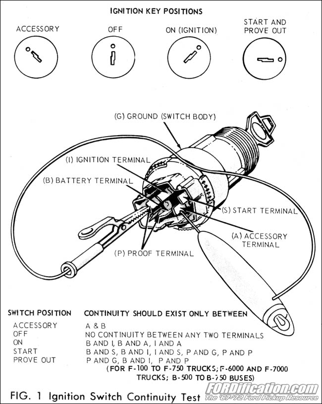
The wiring schematics for the ignition switch of any vehicle can be found not far off from the Internet or in the vehicle service manual. Most estate mechanics run into obscurity profundity in the manner of infuriating to wire a five-pole ignition switch because OEM and replacement switches are not labeled in a pretension that corresponds to the specific vehicle wiring schematic, but to a adequate industry code. In this video I will assist support you think through the basics of your tractor electrical system, particularly the key switch next three positions: off, run, and sta This video instructs how to easily install a JK290A Jinma Ignition Switch along later the proper wire and prong identification.
![[VA_3113] Manual Pallet Jacks Diagram Wiring Diagram](https://static-assets.imageservice.cloud/8132274/caster-parts-diagram-likewise-5-pole-ignition-switch-wiring-diagram.png)