“Wiring diagram from solar panel to breaker box”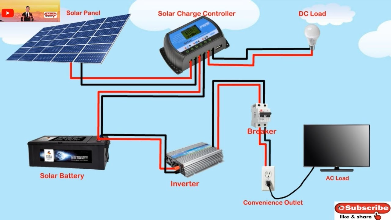
However, installing a solar panel system can be a complex process, requiring a thorough understanding of electrical wiring and safety protocols. In this article, we will provide a comprehensive guide on creating a wiring diagram from solar panel to breaker box, ensuring a safe and efficient connection.
Introduction to Solar Panel Systems
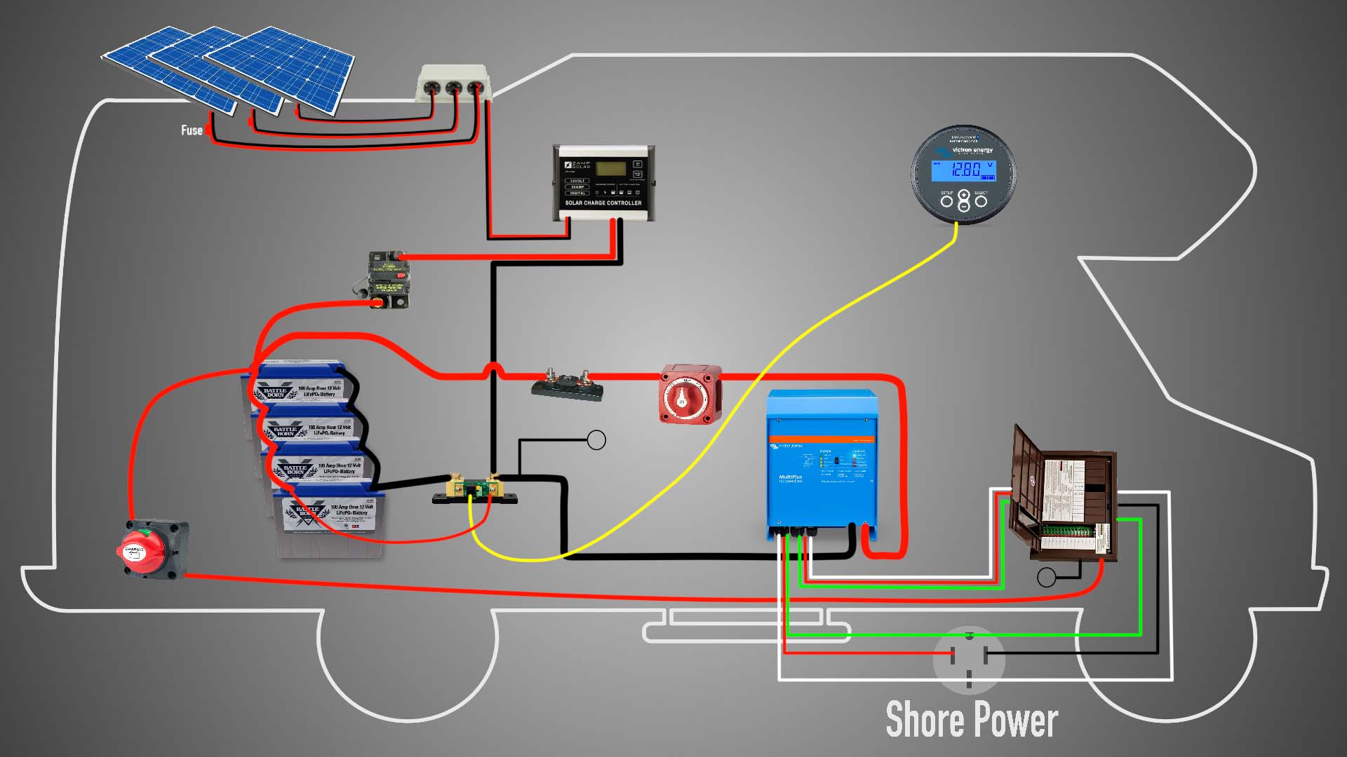
A solar panel system consists of multiple components, including solar panels, a mounting system, an inverter, and a battery bank (optional). The solar panels convert sunlight into direct current (DC) electricity, which is then sent to an inverter that converts the DC power into alternating current (AC) electricity. The AC electricity is then fed into the breaker box, where it is distributed to various circuits throughout the building.
Understanding the Components
Before creating a wiring diagram, it is essential to understand the components involved in the solar panel system:
- Solar Panels: These are the photovoltaic (PV) panels that convert sunlight into DC electricity. Solar panels are typically connected in series and/or parallel to achieve the desired voltage and current output.
- Inverter: This device converts the DC power from the solar panels into AC power, which is compatible with the electrical grid.
- Mounting System: This includes the racks, clamps, and other hardware used to secure the solar panels to the roof or ground.
- Breaker Box: Also known as a panelboard, this is the main electrical distribution point for the building, where the solar panel system connects to the existing electrical infrastructure.
- Grounding System: This is a critical safety component that protects against electrical shock and ensures the system is properly grounded.
Wiring Diagram Components
To create a wiring diagram from solar panel to breaker box, you will need to include the following components:
- Solar Panel Array: Represented by a series of connected rectangles or squares, each symbolizing a solar panel.
- Inverter: Shown as a rectangular box with input and output terminals.
- Breaker Box: Depicted as a panelboard with various circuit breakers and buses.
- Grounding System: Represented by a grounding rod or plate, connected to the solar panel system and the breaker box.
- Wiring and Connectors: Shown as lines and symbols representing the various wires and connectors used to connect the components.

Wiring Diagram Symbols
To create a clear and concise wiring diagram, it is essential to use standardized symbols and notation. The following symbols are commonly used in wiring diagrams:
- Lines and Wires: Represented by solid or dashed lines, depending on the type of wire (e.g., solid for copper, dashed for aluminum).
- Connectors and Terminals: Shown as small circles, squares, or triangles, depending on the type of connector.
- Breakers and Fuses: Represented by rectangular boxes with a diagonal line or a fuse symbol.
- Grounding Symbols: Depicted as a grounding rod or plate, connected to the solar panel system and the breaker box.
Creating the Wiring Diagram
To create a wiring diagram from solar panel to breaker box, follow these steps:
- Start with the Solar Panel Array: Represent the solar panel array as a series of connected rectangles or squares, each symbolizing a solar panel.
- Add the Inverter: Connect the solar panel array to the inverter, using a line and symbol to represent the DC input and AC output.
- Connect to the Breaker Box: Draw a line from the inverter to the breaker box, representing the AC output connection.
- Add Grounding System: Connect the grounding system to the solar panel array, inverter, and breaker box, using a grounding rod or plate symbol.
- Include Circuit Breakers and Fuses: Add breakers and fuses to the diagram, as required, to protect against overcurrent and fault conditions.
- Label and Document: Label each component and wire, and document the wiring diagram with relevant information, such as wire sizes, currents, and voltages.
Safety Considerations
When creating a wiring diagram from solar panel to breaker box, it is essential to consider safety protocols to ensure a safe and efficient installation:
- Comply with Local Regulations: Ensure the wiring diagram complies with local electrical codes and regulations.
- Use Proper Wire Sizes: Choose wire sizes that can handle the maximum current and voltage outputs of the solar panel system.
- Install Grounding System: Ensure the grounding system is properly installed and connected to the solar panel system and the breaker box.
- Test and Inspect: Test and inspect the wiring diagram and installation to ensure it is safe and functioning correctly.
Conclusion
Creating a wiring diagram from solar panel to breaker box requires a thorough understanding of electrical wiring and safety protocols. By following the steps and guidelines outlined in this article, you can create a comprehensive and accurate wiring diagram that ensures a safe and efficient connection between the solar panel system and the breaker box. Remember to always comply with local regulations, use proper wire sizes, and install a grounding system to protect against electrical shock and ensure the system is properly grounded.
Additional Resources
For further information on creating wiring diagrams and installing solar panel systems, refer to the following resources:
- National Electric Code (NEC): A comprehensive guide to electrical wiring and safety protocols.
- Local Electrical Codes: Check with local authorities for specific regulations and guidelines.
- Solar Panel System Installation Guides: Manufacturers’ guides and instructions for installing solar panel systems.
- Electrical Wiring Diagram Software: Utilize software tools, such as AutoCAD or WireCAD, to create and simulate wiring diagrams.
By following the guidelines and using the resources outlined in this article, you can create a safe and efficient wiring diagram from solar panel to breaker box, ensuring a successful and reliable solar panel system installation.

