“Solar wiring diagram for residential use”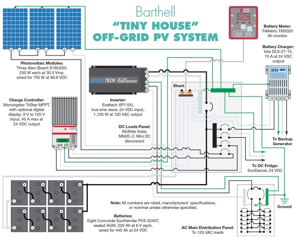
With the help of a well-designed solar wiring diagram, homeowners can harness the energy of the sun to power their homes efficiently and safely. In this article, we will delve into the world of solar wiring diagrams, exploring their importance, components, and step-by-step instructions for creating a reliable and efficient solar wiring system for residential use.
Introduction to Solar Wiring Diagrams
A solar wiring diagram is a visual representation of the electrical connections between various components of a solar power system. It serves as a blueprint for installing, maintaining, and troubleshooting the system, ensuring that it operates at optimal levels. A well-designed solar wiring diagram is essential for residential use, as it helps to:
- Ensure safety: A clear and accurate wiring diagram helps electricians and homeowners identify potential hazards and avoid electrical shocks or fires.
- Optimize performance: By illustrating the correct connections and configurations, a solar wiring diagram ensures that the system operates at maximum efficiency, generating the most energy possible.
- Simplify maintenance: A comprehensive wiring diagram allows homeowners and electricians to quickly identify and replace faulty components, reducing downtime and maintenance costs.
Components of a Solar Wiring Diagram
A typical solar wiring diagram consists of the following components:
- Solar panels: Represented by symbols or icons, solar panels are the primary energy-generating components of the system.
- Inverter: The inverter converts DC power from the solar panels to AC power, suitable for residential use.
- Mounting system: The mounting system, including racks, clamps, and tracking systems, secures the solar panels in place.
- Charge controllers: Charge controllers regulate the flow of energy from the solar panels to the battery bank or inverter.
- Battery bank: A battery bank stores excess energy generated by the solar panels for later use.
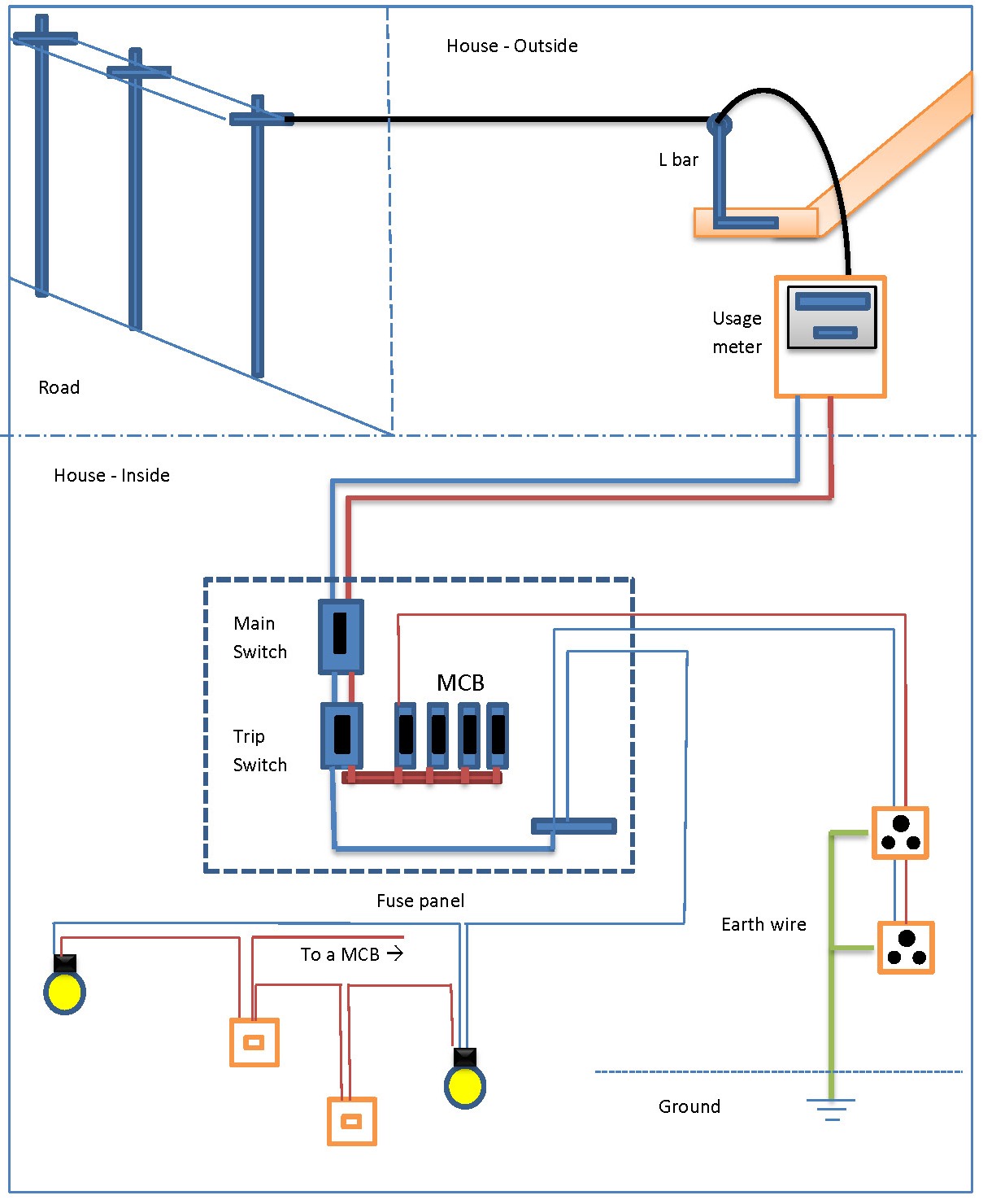
- Load center: The load center, also known as the main electrical panel, distributes AC power to the various circuits in the home.
- Grounding system: The grounding system ensures the safe dissipation of electrical currents to the earth.

Creating a Solar Wiring Diagram
To create a solar wiring diagram for residential use, follow these steps:
- Determine the system size: Calculate the total energy requirements of the home and the number of solar panels needed to meet those demands.
- Choose the components: Select the necessary components, including solar panels, inverter, charge controller, battery bank, and mounting system.
- Design the system layout: Sketch the physical layout of the system, including the location of the solar panels, inverter, and other components.
- Create the wiring diagram: Using a computer-aided design (CAD) software or a graphical tool, create a visual representation of the electrical connections between the components.
- Include safety features: Incorporate safety features, such as fuses, circuit breakers, and ground fault protection, to ensure the system operates safely.
- Verify local electrical codes: Ensure the wiring diagram complies with local electrical codes and regulations.
Step-by-Step Instructions for Creating a Solar Wiring Diagram
Here’s a detailed example of creating a solar wiring diagram for a residential system:
System Specifications:
- 5 kW solar array
- 1 x 5 kW inverter
- 1 x charge controller
- 1 x battery bank (12V, 200Ah)
- 1 x load center (main electrical panel)
Wiring Diagram:
- Solar Panel Array:
- Connect the positive terminal of each solar panel to the positive terminal of the next panel (series connection).
- Connect the negative terminal of each solar panel to the negative terminal of the next panel (series connection).
- Connect the combined positive and negative terminals to the charge controller.
- Charge Controller:
- Connect the input terminals of the charge controller to the solar panel array.
- Connect the output terminals of the charge controller to the battery bank.
- Battery Bank:
- Connect the positive terminal of the battery bank to the positive terminal of the inverter.
- Connect the negative terminal of the battery bank to the negative terminal of the inverter.
- Inverter:
- Connect the input terminals of the inverter to the battery bank.
- Connect the output terminals of the inverter to the load center.
- Load Center:
- Connect the input terminals of the load center to the inverter.
- Connect the output terminals of the load center to the various circuits in the home.
Grounding and Safety Features:
- Connect the grounding terminal of the inverter to the grounding system.
- Install fuses or circuit breakers to protect against overcurrent conditions.
- Incorporate ground fault protection to detect and interrupt ground faults.
Best Practices and Tips
When creating a solar wiring diagram for residential use, keep the following best practices and tips in mind:
- Use a clear and consistent labeling system to identify components and connections.
- Ensure the wiring diagram is scalable and easy to read.
- Include a legend or key to explain the symbols and abbreviations used.
- Verify the wiring diagram against local electrical codes and regulations.
- Consider using a CAD software or graphical tool to create the wiring diagram.
Conclusion
A well-designed solar wiring diagram is essential for residential use, ensuring the safe and efficient operation of the solar power system. By following the steps outlined in this article and incorporating best practices and tips, homeowners and electricians can create a reliable and efficient solar wiring system. Remember to always verify the wiring diagram against local electrical codes and regulations, and consider consulting a professional if you’re unsure about any aspect of the design or installation process. With the right solar wiring diagram, you can harness the power of the sun to energize your home, reducing your reliance on fossil fuels and minimizing your carbon footprint.


