“House solar power electrical schematics”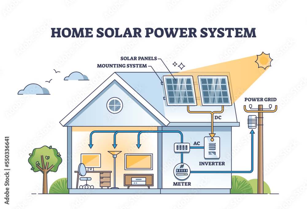
A well-designed solar power system can provide a reliable and efficient source of electricity, but it requires a thorough understanding of electrical schematics. In this article, we will delve into the world of house solar power electrical schematics, exploring the key components, design considerations, and best practices for creating a safe and efficient solar power system.
Introduction to Solar Power Electrical Schematics
A solar power electrical schematic is a visual representation of the electrical connections and components that make up a solar power system. It is a crucial tool for designing, installing, and maintaining a solar power system, as it provides a clear and concise overview of the system’s layout and functioning. A typical solar power electrical schematic includes the following components:
- Solar Panels: These are the photovoltaic (PV) panels that convert sunlight into electrical energy.
- Charge Controller: This device regulates the flow of energy from the solar panels to the battery bank, preventing overcharging and ensuring the batteries are properly maintained.
- Battery Bank: This is a group of deep cycle batteries that store excess energy generated by the solar panels for later use.
- Inverter: This device converts the DC (direct current) power from the battery bank into AC (alternating current) power, which is usable in the home.
- Load Center: This is the main electrical panel that distributes power to the various circuits in the home.
- Grounding System: This is a critical safety feature that protects the system and its users from electrical shock.
Design Considerations for House Solar Power Electrical Schematics
When designing a house solar power electrical schematic, there are several key considerations to keep in mind:
- System Size: The size of the solar power system will depend on the energy requirements of the home, as well as the available space and budget.
- Panel Orientation and Angle: The orientation and angle of the solar panels can significantly impact their efficiency, with south-facing panels typically being the most effective.
- Shading: Shading from trees, buildings, or other obstructions can reduce the efficiency of the solar panels, so it is essential to take this into account when designing the system.
- Battery Bank Sizing: The size of the battery bank will depend on the energy requirements of the home, as well as the depth of discharge (DOD) of the batteries.
- Inverter Selection: The inverter should be selected based on the size of the system, the type of batteries used, and the energy requirements of the home.
- Grounding and Bonding: A proper grounding and bonding system is essential to ensure the safety of the system and its users.


Best Practices for Creating a House Solar Power Electrical Schematic
To create a safe and efficient house solar power electrical schematic, follow these best practices:
- Use a Standardized Symbol Set: Use a standardized set of symbols and notation to ensure clarity and consistency in the schematic.
- Include All Components: Include all components in the schematic, including the solar panels, charge controller, battery bank, inverter, load center, and grounding system.
- Show Connections and Wiring: Clearly show all connections and wiring between components, including the size and type of wire used.
- Include Safety Features: Include safety features such as fuses, circuit breakers, and ground fault protection.
- Consider Future Expansion: Consider future expansion and upgrades when designing the system, and leave room for additional components or circuits.
Common Mistakes to Avoid in House Solar Power Electrical Schematics
When creating a house solar power electrical schematic, there are several common mistakes to avoid:
- Inadequate Grounding: Inadequate grounding can lead to safety hazards and system failures.
- Insufficient Overcurrent Protection: Insufficient overcurrent protection can lead to damage to the system and its components.
- Incorrect Component Selection: Incorrect component selection can lead to system inefficiencies and failures.
- Poor Wiring and Connections: Poor wiring and connections can lead to system failures and safety hazards.
- Lack of Maintenance Access: Lack of maintenance access can make it difficult to perform routine maintenance and repairs.
Software Tools for Creating House Solar Power Electrical Schematics
There are several software tools available for creating house solar power electrical schematics, including:
- Autodesk AutoCAD: A popular computer-aided design (CAD) software that can be used to create detailed and accurate schematics.
- SketchUp: A user-friendly CAD software that can be used to create 3D models and schematics.
- SolarPathfinder: A software tool specifically designed for solar power system design and simulation.
- HOMER: A software tool that can be used to design and simulate off-grid and grid-tie solar power systems.
- PVSYST: A software tool that can be used to design and simulate solar power systems, including grid-tie and off-grid systems.
Conclusion
Creating a house solar power electrical schematic requires a thorough understanding of electrical principles, as well as knowledge of solar power systems and their components. By following best practices and avoiding common mistakes, homeowners and solar installers can create safe and efficient solar power systems that provide reliable and renewable energy. Whether you are designing a new system or upgrading an existing one, a well-designed electrical schematic is essential for ensuring the safety and efficiency of the system. With the right software tools and a bit of practice, anyone can create a professional-looking and functional house solar power electrical schematic.


