“Residential solar power wiring diagram”
These systems not only help reduce our reliance on fossil fuels but also provide a significant reduction in energy costs. However, installing a residential solar power system can be a complex process, requiring careful planning and execution. One of the most critical aspects of a solar power system is the wiring diagram, which ensures the safe and efficient transmission of electricity from the solar panels to the electrical panel and eventually to the appliances. In this article, we will delve into the world of residential solar power wiring diagrams, exploring the key components, best practices, and safety considerations.
Introduction to Residential Solar Power Systems
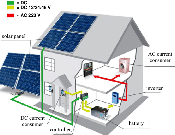
A residential solar power system consists of several key components, including:
- Solar Panels: These are the photovoltaic (PV) panels that convert sunlight into electrical energy.
- Mounting System: This is the framework that supports the solar panels and ensures they are securely fastened to the roof or ground.
- Inverter: This device converts the DC power generated by the solar panels into AC power, which is usable in the home.
- Electrical Panel: This is the main distribution panel that receives the AC power from the inverter and distributes it to the various appliances and circuits in the home.
- Wiring and Connectors: These are the components that connect the solar panels, inverter, and electrical panel, ensuring the safe and efficient transmission of electricity.
Residential Solar Power Wiring Diagram Components
A typical residential solar power wiring diagram consists of the following components:
- Solar Panel Array: This represents the group of solar panels connected together in series and parallel to form a single electrical circuit.
- Inverter Output: This represents the output of the inverter, which is typically a 240V AC circuit.
- Electrical Panel: This represents the main distribution panel that receives the AC power from the inverter.
- Grounding System: This is a critical component that ensures the safe operation of the solar power system by providing a path to ground for fault currents.
- Disconnects: These are devices that allow for the isolation of the solar power system from the electrical panel and inverter.
- Fuses and Circuit Breakers: These are devices that protect the solar power system from overcurrent conditions and provide a means of disconnecting the system in case of a fault.
Best Practices for Residential Solar Power Wiring Diagrams
To ensure the safe and efficient operation of a residential solar power system, the following best practices should be followed:
- Use a licensed electrician: The installation of a residential solar power system should only be performed by a licensed electrician who has experience with solar power systems.
- Follow local electrical codes: The wiring diagram should comply with local electrical codes and regulations, such as the National Electric Code (NEC).
- Use proper sizing and rating: The wiring and connectors should be properly sized and rated for the application, taking into account the maximum power output of the solar panels and inverter.
- Ensure proper grounding: The grounding system should be designed to provide a safe path to ground for fault currents and to prevent electrical shock.
- Test and inspect the system: The solar power system should be thoroughly tested and inspected before energization to ensure that it is operating safely and efficiently.
Safety Considerations for Residential Solar Power Wiring Diagrams
The installation of a residential solar power system poses several safety risks, including:
- Electrical shock: The solar power system can produce electrical shock if not properly installed or maintained.
- Fire hazards: The solar power system can pose a fire hazard if the wiring and connectors are not properly sized and rated.
- Overcurrent conditions: The solar power system can experience overcurrent conditions, which can cause damage to the system and pose a safety risk.
To mitigate these safety risks, the following precautions should be taken:
- Use personal protective equipment: Electricians and installation personnel should wear personal protective equipment, such as hard hats, safety glasses, and gloves, when working with electrical systems.
- De-energize the system: The solar power system should be de-energized before performing any maintenance or repairs.
- Use lockout/tagout procedures: The solar power system should be locked out and tagged out to prevent accidental energization during maintenance or repairs.
Common Residential Solar Power Wiring Diagram Configurations
There are several common configurations for residential solar power wiring diagrams, including:
- Series configuration: In this configuration, the solar panels are connected in series to form a single electrical circuit.
- Parallel configuration: In this configuration, the solar panels are connected in parallel to form multiple electrical circuits.
- Combination configuration: In this configuration, the solar panels are connected in a combination of series and parallel to form multiple electrical circuits.
Each configuration has its own advantages and disadvantages, and the choice of configuration will depend on the specific requirements of the solar power system.
Conclusion
In conclusion, a residential solar power wiring diagram is a critical component of a solar power system, ensuring the safe and efficient transmission of electricity from the solar panels to the electrical panel and eventually to the appliances. By following best practices and safety considerations, homeowners can ensure that their solar power system operates safely and efficiently, providing a significant reduction in energy costs and a reduced reliance on fossil fuels. Whether you are a licensed electrician or a homeowner, it is essential to understand the key components and configurations of a residential solar power wiring diagram to ensure a safe and successful installation.
References
- National Electric Code (NEC)
- International Association of Electrical Inspectors (IAEI)
- National Fire Protection Association (NFPA)
- Solar Energy Industries Association (SEIA)
- Underwriters Laboratories (UL)
Appendix
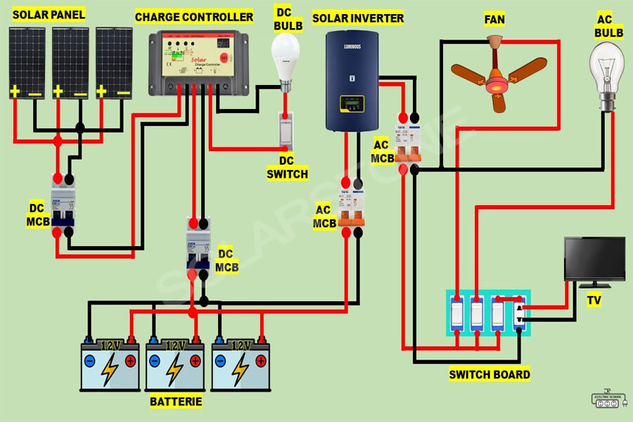
The following is a sample residential solar power wiring diagram:
[Insert sample wiring diagram]
This diagram illustrates a typical residential solar power system with a series configuration of solar panels, an inverter, and an electrical panel. The diagram also shows the grounding system, disconnects, and fuses and circuit breakers. This is just one example of a residential solar power wiring diagram, and the specific configuration will depend on the requirements of the solar power system.


