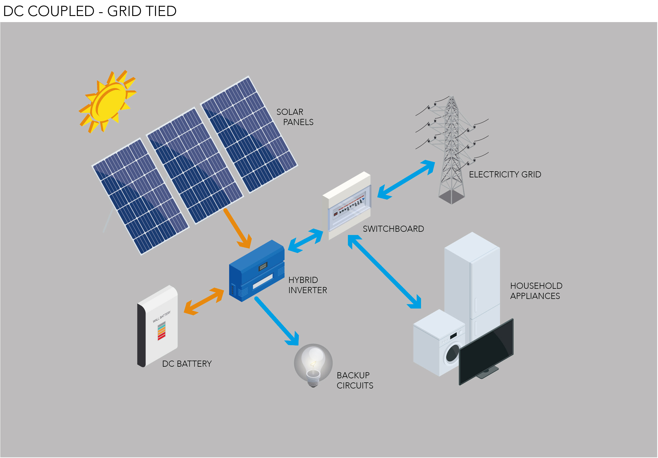
“Grid-tied PV system wiring layout”
A grid-tied PV system is a type of PV system that connects to the utility grid, allowing homeowners and businesses to generate their own electricity while still having access to the grid when needed. In this article, we will delve into the wiring layout of a grid-tied PV system, exploring the key components, design considerations, and best practices for a safe and efficient installation.
Introduction to Grid-tied PV Systems
A grid-tied PV system consists of several key components, including:
- PV Modules: Also known as solar panels, these are the devices that convert sunlight into electrical energy.
- Inverter: This device converts the DC power generated by the PV modules into AC power, which is usable by the grid and electrical appliances.
- Mounting System: This includes the racking, clamps, and other hardware used to secure the PV modules to the roof or ground.
- Electrical Panel: This is the main electrical panel that distributes power to the building’s electrical system.
- Utility Meter: This meter measures the amount of electricity generated by the PV system and fed back into the grid.
Wiring Layout Considerations
When designing the wiring layout for a grid-tied PV system, several factors must be considered to ensure a safe and efficient installation. These include:
- System Voltage: The system voltage will determine the type and size of wiring required. Most residential grid-tied PV systems operate at 240V or 480V.
- System Current: The system current will also determine the type and size of wiring required. The current will depend on the number and type of PV modules, as well as the inverter’s maximum power point tracking (MPPT) capacity.
- Distance and Routing: The distance between the PV modules, inverter, and electrical panel will affect the wiring layout. Wires should be routed to minimize distance and avoid obstacles.
- Protection and Grounding: The wiring layout must include proper protection and grounding to prevent electrical shock and ensure system safety.
- Code Compliance: The wiring layout must comply with local electrical codes and regulations, such as the National Electric Code (NEC) in the United States.

Wiring Layout Components
The wiring layout for a grid-tied PV system includes several key components, including:
- PV Module Connectors: These connectors link the PV modules together and to the inverter.
- Inverter Output Cables: These cables connect the inverter to the electrical panel.
- AC Cables: These cables connect the electrical panel to the utility meter and the rest of the electrical system.
- Grounding and Bonding: This includes the grounding wires and bonding connections between the PV modules, inverter, and electrical panel.
- Surge Protection Devices: These devices protect the system from power surges and lightning strikes.
Best Practices for Wiring Layout
To ensure a safe and efficient installation, follow these best practices for wiring layout:
- Keep Wires Organized: Use wire management systems, such as cable ties and conduit, to keep wires organized and secure.
- Use Proper Wire Sizing: Use wires that are sized correctly for the system voltage and current.
- Avoid Overloading: Avoid overloading wires and cables, which can lead to overheating and system failure.
- Use Proper Connectors: Use connectors that are designed for the specific application and meets the system’s voltage and current requirements.
- Test and Inspect: Test and inspect the wiring layout before and after installation to ensure it meets code requirements and is safe for operation.
Code Requirements and Compliance
The wiring layout for a grid-tied PV system must comply with local electrical codes and regulations. In the United States, the NEC requires that:
- Wiring be sized correctly: Wires must be sized to handle the maximum current and voltage of the system.
- Grounding and bonding be proper: The system must be properly grounded and bonded to prevent electrical shock.
- Surge protection be installed: Surge protection devices must be installed to protect the system from power surges and lightning strikes.
- Labeling and signage be clear: The system must be labeled and signed clearly to identify the components and wiring.
Conclusion
In conclusion, the wiring layout for a grid-tied PV system is a critical component of a safe and efficient installation. By considering system voltage, current, distance, and routing, as well as protection and grounding, installers can design a wiring layout that meets code requirements and ensures reliable operation. By following best practices and using proper components and materials, installers can ensure a safe and efficient installation that will provide years of clean and sustainable electricity.
References
- National Electric Code (NEC): The NEC is a comprehensive guide to electrical codes and regulations in the United States.
- International Association of Electrical Inspectors (IAEI): The IAEI provides training and resources for electrical inspectors and installers.
- Solar Energy Industries Association (SEIA): The SEIA provides resources and guidance for solar installers and industry professionals.
- Institute of Electrical and Electronics Engineers (IEEE): The IEEE provides standards and guidelines for electrical systems, including solar PV systems.
Appendix
The following figures and diagrams illustrate the wiring layout for a typical grid-tied PV system:
- Figure 1: System Schematic
- Figure 2: Wiring Diagram
- Figure 3: Grounding and Bonding Diagram
- Figure 4: Surge Protection Device Installation
Note: These figures and diagrams are for illustration purposes only and may not be used for actual installation purposes. Always consult local electrical codes and regulations, as well as manufacturer’s instructions, for specific installation requirements.


