“RV solar wiring diagram”
Not only does it reduce reliance on traditional energy sources, but it also provides a cost-effective and environmentally friendly way to power your recreational vehicle. However, installing a solar panel system on your RV can be a daunting task, especially when it comes to wiring. In this article, we will provide a comprehensive guide to RV solar wiring diagrams, including the essential components, wiring configurations, and safety considerations.
Introduction to RV Solar Systems
Before we dive into the wiring diagram, it’s essential to understand the basic components of an RV solar system. A typical RV solar system consists of:
- Solar Panels: These are the photovoltaic (PV) panels that convert sunlight into electrical energy.
- Charge Controller: This device regulates the flow of energy from the solar panels to the batteries, preventing overcharging and ensuring the batteries are charged safely.
- Batteries: These store the excess energy generated by the solar panels for later use.
- Inverter/Charger: This device converts the DC power from the batteries to AC power, which is usable by the RV’s appliances.
- Wiring and Electrical Components: This includes the wires, fuses, and circuit breakers that connect the various components of the system.
Understanding RV Solar Wiring Diagrams
An RV solar wiring diagram is a visual representation of the electrical connections between the various components of the system. It’s essential to understand the diagram to ensure that the system is installed correctly and safely. A typical RV solar wiring diagram will include the following elements:
- Panel Wiring: This shows the connection between the solar panels and the charge controller.
- Charge Controller Wiring: This illustrates the connection between the charge controller and the batteries.
- Battery Wiring: This shows the connection between the batteries and the inverter/charger.
- Inverter/Charger Wiring: This illustrates the connection between the inverter/charger and the RV’s electrical panel.
- Grounding and Bonding: This shows the connection between the system’s components and the RV’s chassis, ensuring that the system is properly grounded and bonded.

Wiring Configurations
There are several wiring configurations to consider when installing an RV solar system. The most common configurations include:

- Series Wiring: In this configuration, the solar panels are connected in series, with the positive terminal of one panel connected to the negative terminal of the next panel. This configuration is suitable for small systems with few panels.
- Parallel Wiring: In this configuration, the solar panels are connected in parallel, with the positive terminals connected together and the negative terminals connected together. This configuration is suitable for larger systems with multiple panels.
- Series-Parallel Wiring: This configuration combines series and parallel wiring, allowing for more flexibility and scalability.
Safety Considerations
When working with electrical systems, safety is paramount. Here are some essential safety considerations to keep in mind:
- Use Proper Wiring and Connectors: Use high-quality, UV-resistant wiring and connectors specifically designed for solar panel systems.
- Follow Manufacturer Instructions: Follow the manufacturer’s instructions for the various components, including the solar panels, charge controller, batteries, and inverter/charger.
- Grounding and Bonding: Ensure that the system is properly grounded and bonded to prevent electrical shock and fires.
- Fuses and Circuit Breakers: Install fuses and circuit breakers to protect the system from overloads and short circuits.
- Regular Maintenance: Regularly inspect and maintain the system to ensure that it’s functioning correctly and safely.
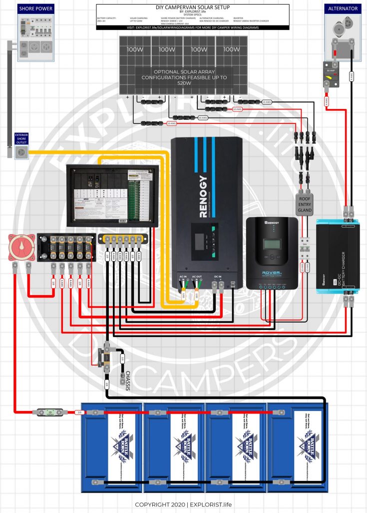
Example RV Solar Wiring Diagram
Here is an example RV solar wiring diagram for a small system with two solar panels, a charge controller, two batteries, and an inverter/charger:
Panel Wiring
- Solar Panel 1: Positive terminal connected to Solar Panel 2: Negative terminal
- Solar Panel 2: Positive terminal connected to Charge Controller: Input terminal
Charge Controller Wiring
- Charge Controller: Output terminal connected to Battery 1: Positive terminal
- Charge Controller: Output terminal connected to Battery 2: Positive terminal
Battery Wiring
- Battery 1: Negative terminal connected to Battery 2: Negative terminal
- Battery 1: Positive terminal connected to Inverter/Charger: Input terminal
- Battery 2: Positive terminal connected to Inverter/Charger: Input terminal
Inverter/Charger Wiring
- Inverter/Charger: Output terminal connected to RV Electrical Panel: Input terminal
Grounding and Bonding
- Solar Panel 1: Negative terminal connected to RV Chassis: Grounding point
- Solar Panel 2: Negative terminal connected to RV Chassis: Grounding point
- Charge Controller: Grounding terminal connected to RV Chassis: Grounding point
- Batteries: Negative terminals connected to RV Chassis: Grounding point
- Inverter/Charger: Grounding terminal connected to RV Chassis: Grounding point
Conclusion
Installing an RV solar system can be a complex task, but with a clear understanding of the wiring diagram and safety considerations, you can ensure a safe and efficient installation. Remember to follow the manufacturer’s instructions, use proper wiring and connectors, and regularly maintain the system to ensure that it’s functioning correctly. By following these guidelines, you can enjoy the benefits of solar power and reduce your reliance on traditional energy sources.
Recommended Tools and Materials
- Solar panels
- Charge controller
- Batteries
- Inverter/charger
- Wiring and connectors (UV-resistant)
- Fuses and circuit breakers
- Grounding and bonding equipment
- Multimeter and testing equipment
- Safety gear (gloves, safety glasses, etc.)
Additional Resources
- National Electrical Code (NEC) guidelines for solar panel systems
- Manufacturer’s instructions for the various components
- Online forums and communities for RV solar enthusiasts
- Local electrical inspectors and professionals for guidance and support
By following the guidelines and recommendations outlined in this article, you can create a safe and efficient RV solar wiring diagram that meets your energy needs and provides a reliable source of power for your recreational vehicle. Happy camping!