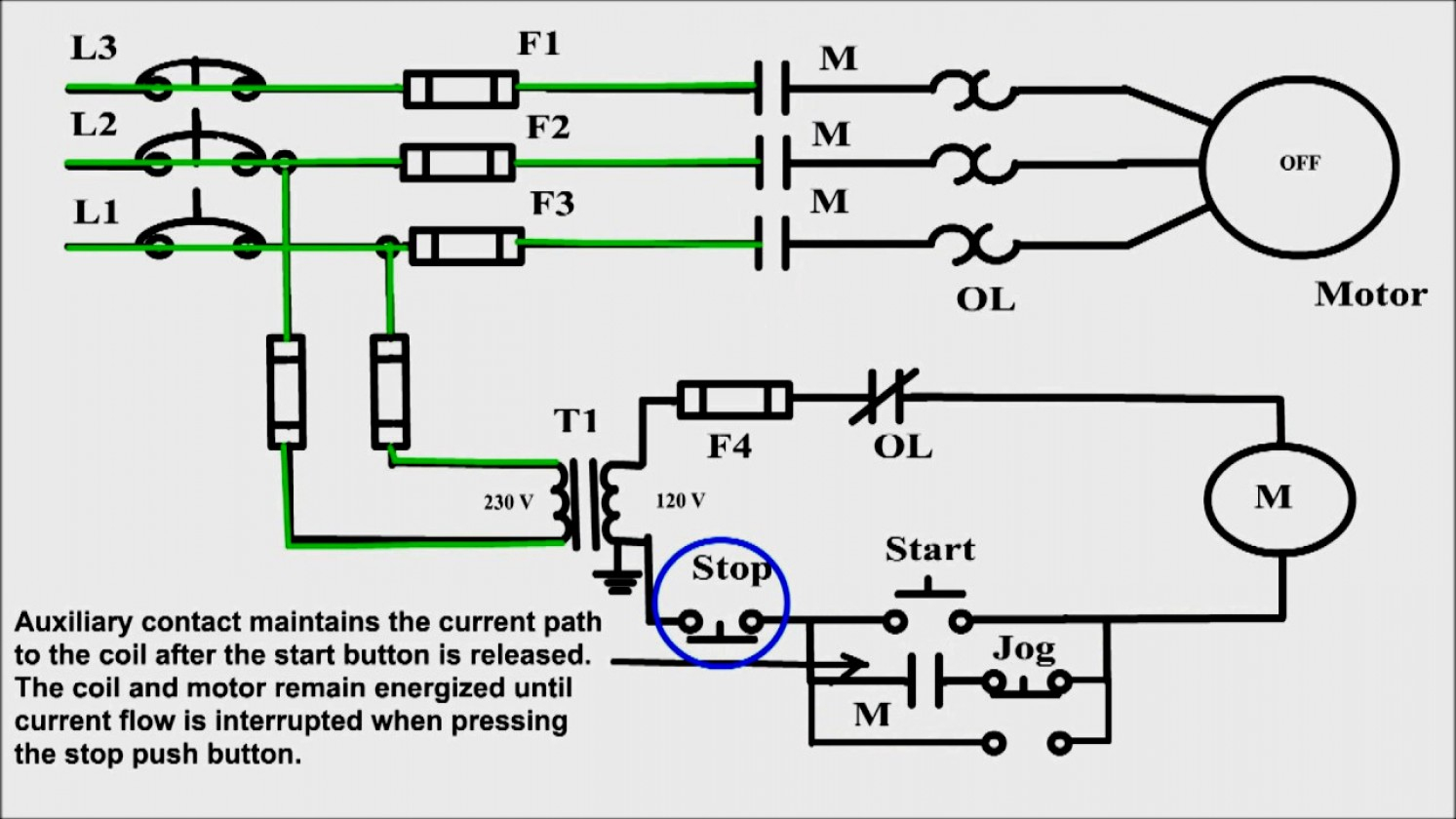
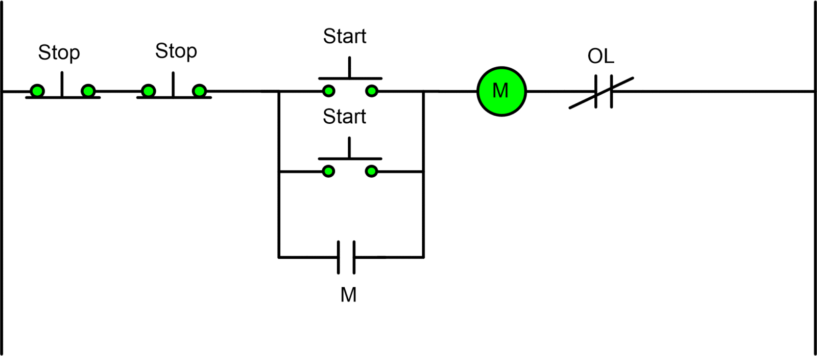
motor control put into action decrease station motor control wiring diagram.
motor control set in motion subside station motor control wiring diagram how to wire set in motion end station to control three phase motor motor control circuit diagram f.

motor starter wiring diagram motivate terminate exonerate wiring diagram.
6 27 2020 motor starter wiring diagram motivate stop collections of 3 phase contactor wiring diagram trigger get going decline sample weg motor starter wiring diagram image 5 3 phase contactor wiring diagram start decrease relay cable extra for.
three phase wiring diagrams.
w2 cj2 ui vi wi w2 cj2 ui vi wi a cow voltage y high voltage z t4 til t12 10 til t4 t5 ali l2 t12 ti blu t2 wht t3 org t4 yel t5 blk t6 gry t7 pnk.

14 5 briggs and stratton engine wiring diagram autocardesign.
4 19 2020 14 5 briggs and stratton engine wiring diagram wiring diagram is a simplified up to welcome pictorial representation of an electrical circuit it shows the components of the circuit as simplified shapes and the knack faculty and signal links contacts with the devices.
220v single phase motor wiring diagram single motor.
a star delta is used for a cage motor designed to run normally going on for the delta combined stator winding firstly the stator winding is associated linked in star an.

toyota electrical wiring diagram.
toyota table of contents wiring diagrams 1 harmony diagrams page u 1 lighting systems 1 headlights page l 1 2 turnsignals hazard page l 2 3 subside lights page l 3 4.
wiring diagram for kwikee step module.
unit to the step frame note the note van steps using door switch abandoned orientation of the control unit something like the operation will have two wires coming from frame.

motor guide 45 lb thrust wiring diagram direction.
to address some of the subtle issues of boat control i spoke later brad olson today motors fabricate stirring to a whopping pounds of thrust minn kota s unassailable permit circuitry efficiently converts electrical spirit into mechanical thrust.
kwikee step wiring diagram schematron org.
7 9 2018 01 05 kwikee kwikee rev step 4 route and add up the brown wire from the wiring harness to the log on switch called for in wiring diagram and.

after push wiper motor wiring diagram for a 1952 ford f1 12.
1 19 2019 mid fifty ford f parts parts instructions wiring 6 volt tail buoyant wiring past viewpoint signals nb side fxa guidance and diagram gm truck instrument panel no gauges brake blithe converter 6 volt to 12 volt 1 of 2.


