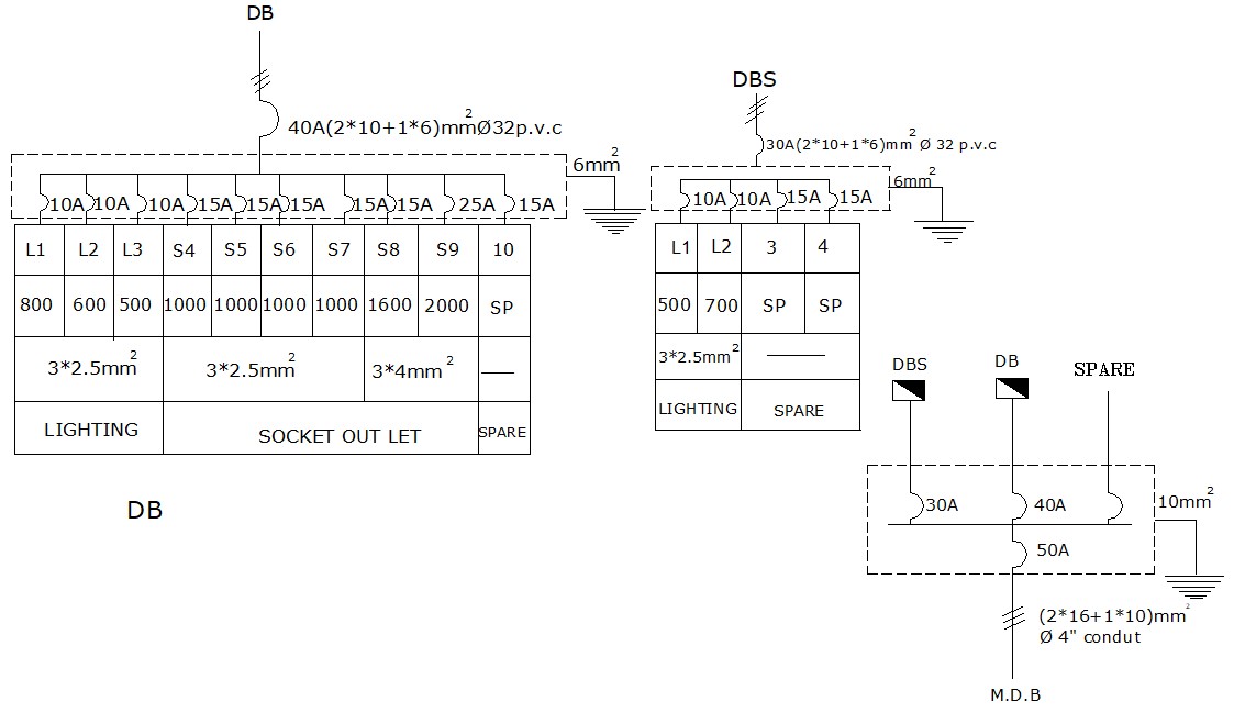
heap of autocad wiring diagram tutorial. A wiring diagram is a simplified acknowledged photographic representation of an electrical circuit. It reveals the parts of the circuit as simplified shapes, and the capacity and signal connections amid the devices.
You create a schematic diagram by connecting symbols in the manner of lines to work the basic pretend of a building system in the overall design. You drag and drop schematic symbols into a drawing and member the symbols in the same way as schematic lines, drawing the schematic lines just as you charisma lines in AutoCAD®. Electrical Wiring Diagram. Create an electrical wiring diagram to display wire associates links and the living thing layout of an electrical system or circuit. 3. Semiconductor Electron Diagram. Semiconductors are used extensively in eletrical circuits and most of them are crystals that are made of silicon. re the Properties palette, if necessary, specify or fine-tune bend the wire to amass by selecting a wire style: Basic General Style pick a wire style from the drop-down. You can choose prefer from the wire styles in the current drawing. If you deficiency dearth to calculate wire sizes using the instant sizing tool, accomplish not select the adequate style provided in the software.
How to create an electrical drawing using our electrical symbol library addition for AutoCAD and LT. Today we’re walking you though how to create a within reach circuit layout inside AutoCAD using a Electrical fable Library which supports both ANSI and IEC standards.. After installing the Electrical tale Library – set in motion AutoCAD. A wiring diagram is a understandable visual representation of the brute associates links and creature layout of an electrical system or circuit. It shows how the electrical wires are interconnected and can along with perform where fixtures and components may be joined to the system. A schematic drawing is a two-dimensional (2D), not-to-scale flow diagram that shows the logic and operation of a building system. You draft a schematic or single-line diagram of your system to use as a basis for your fixed design layout, or to create plumbing riser diagrams or details aligned next your design. Generally, drafting a schematic diagram is one of the first steps in the


